3dsystems20
My work during the course Design and Implementation of 3D Graphics Systems
This project is maintained by hallpaz
3D Graphics Systems Course - IMPA 2020
Professor Luiz Velho
Hallison Paz, 1st year PhD student
Assignment 1 - Exploring PyTorch3D library
The objective of this assignment is to get familiarized with the AI Graphics platform Pytorch3D. To achieve this, I read though the available documentation and tutorials and started doing some experiments focused on 3D modeling topic.
Creating primitives with PyTorch3D
PyTorch3D was designed to work with 3D meshes. Because of that, I started trying to understand how to operate with the Mesh data structure of the library. While running the tutorials, I discovered that the library has one module called “utils” where there are functions to generate a sphere and a torus meshes as primitives. It seemed to me that writing my own functions to generate other primitive forms could be a good exercise to understand the PyTorch3D meshes. Besides that, if I managed this well, this work could be submitted as a contribution to the library as it’s open source.
Simple primitives
First, inspired by the availability of primitives in Blender and Unity, I created a cube and a cylinder, basic shapes that were missing in PyTorch3D. The shapes were added in a manner fully compatible with the library.
-
Source Code for the cube.
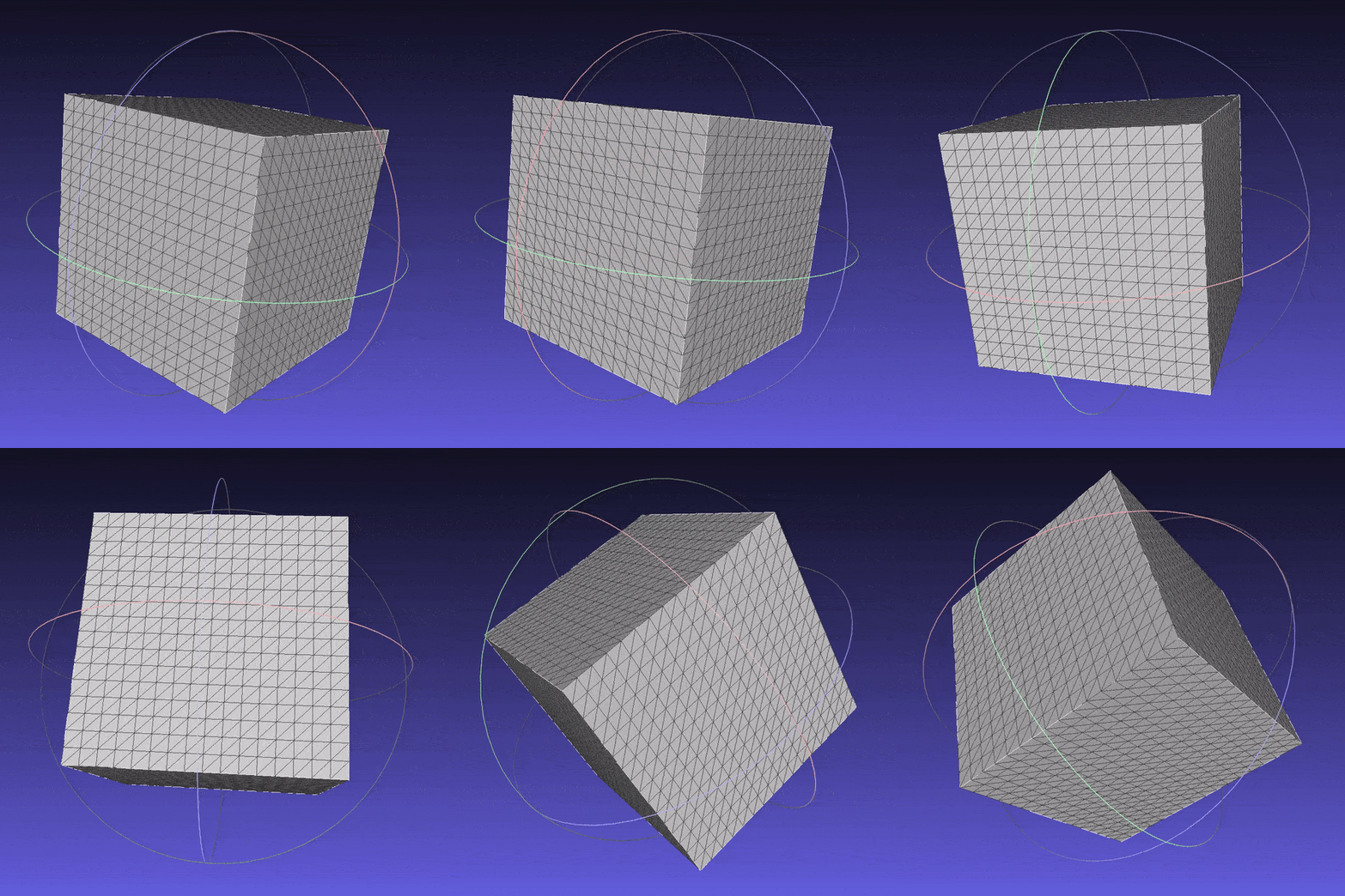 Cube mesh subdivided 4 times.
 -
Source Code for the cylinder.
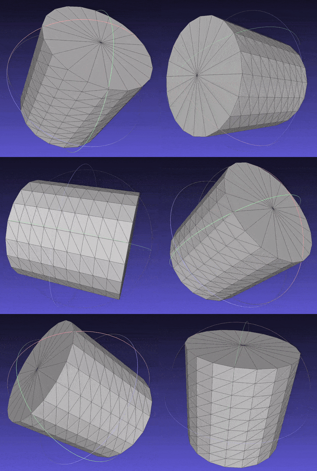
Cylinder mesh.
Solids of revolution
After these well succeeded attempts, I wrote a function to generate meshes of surfaces of revolution. With this function, we would be able to generate many different meshes only varying the function that describes the generatrix curve. I added a parameter to indicate whether or not the mesh should be closed, with True as the default value; in this case, I implemented a naive approach, just connecting the boundary vertices to a single point on the bottom or the top of the surface. The surfaces were computed as a revolution over the Z axis, using the following parametrization:
- (x, y, z) = (ucos(v), usin(v), f(u))
- 0 <= u <= 1; 0 <= v < PI
-
f is a real function that defines the generatrix curve
- Source Code for the revolution surface.
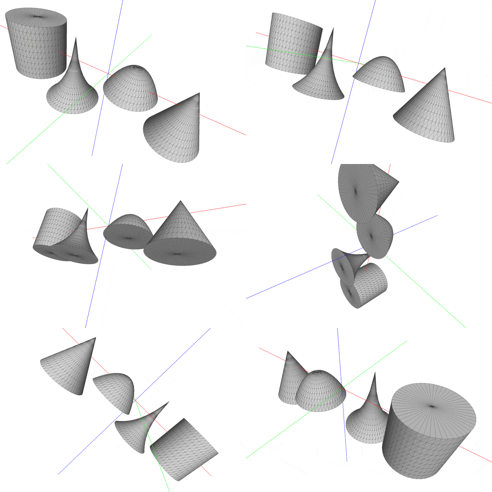 Some meshes of revolution. Check all samples on “data/meshes)” directory.
Deforming Shapes
After creating new synthetic meshes compatible with Pytorch3D, I decided to explore the tutorial Deform a source mesh to form a target mesh using 3D loss functions. The main goal was to understand the applicability of the library in the optimization of a mesh geometry using loss functions and backpropagation.
The example code deforms a refined ico-sphere into a dolphin mesh using the chamfer distance and other three different metrics related to regularization and smoothness of the mesh: an edge length loss, a normal consistency loss and a laplacian regularizer. The example achieves a very good result under these conditions. However, during research and development sometimes things don’t run so “smoothly” (did you get this? 🥁). Thinking about some troublesome past experiences, I decided to remove the normalization step and run some experiments deforming my own synthetic meshes as I could test the following situations:
- Low resolution meshes
- High curvature edges (as in the cube)
- High valence vertices (the closure solids of revolution)
- Meshes with peaks (rotation of arctangent or exponential, for instance)
Experiments with the cube
Experiments on situations (1) and (2) are written in non_smooth_experiments notebook). In this case, I tried to deform a cube into itself and check if I would get something near the original mesh. Although a cube can be represented by a very simple mesh - using only 8 vertices - the first experiment I did, using low resolution and all loss functions, resulted in a degenerated mesh.
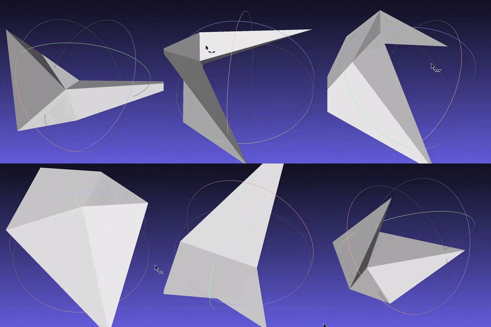 Degenerated cube (low resolution case)
After this, I decided to run experiments using cubes in different levels of resolution with and without the regularization losses. The meshes I obtained as results can be found on “data/meshes/non-smooth)” directory.
Using only the Chamfer distance, I could always get a cube as output. When I added the regularization losses, the cube meshes with lower resolutions converged to other shapes; those with higher resolutions became a cube with “smooth edges”, attenuating the curvature.
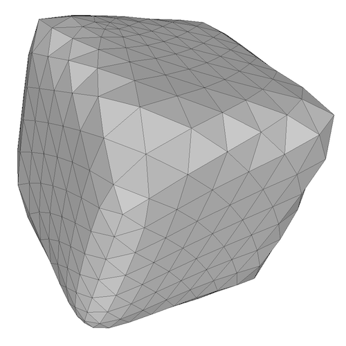 Smoothed cube
Experiments with solids of revolution
Experiments on situations (3) and (4) are written in fairly_smooth_experiments notebook). In this case, I just created some solid of revolution, arranged them into pairs and tried to deform one into another. I didn’t test all possible combinations as it would take a long time (I used my own cpu); besides that, all meshes had a reasonable resolution (around 5000 vertices) and I used all loss functions with the same weights proposed in the example code.
I found the results in these case were very poor, even worse than what I expected. First, I experimented with 1600 iterations, then I tried with 2400 iterations as I thought the missing normalization step could have impacted the performance. With more iterations, the results got a little better, but there were still very bad artifacts such as self intersecting polygons and a high imbalance in vertices concentration. In many cases we can see some highly refined regions on the mesh while another region contains few vertices.
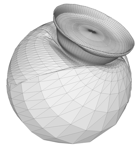 Deforming cone into sphere
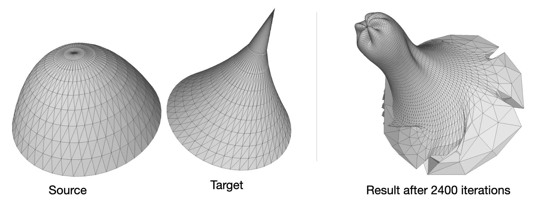 Deforming a paraboloid into a hiperboloid (modified with a peak)
While reflecting about these results, I decided to use the same mesh of the example code to check if my version of the code had any bug. I used the same ico-sphere as the source mesh and I ran the experiment both with and without the normalization step. With the normalization step, I got the same good result of the example code, but without the normalization step, there were some parts of the mesh where we can see the same kind of artifacts I noticed in the previous experiments.
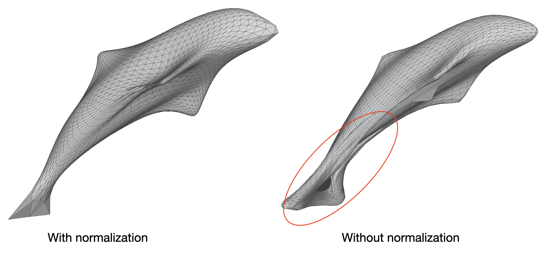
In the example notebook there is a comment stating that normalization affects only speed of convergence.
“Note that normalizing the target mesh, speeds up the optimization but is not necessary!”
I wonder if this is really true for any case. If this is really true, it seems that the impact on speed is huge, since we added 400 iterations (20% more) and still we did not converge to a good solution. I think it’s an issue that needs more investigation in a future work. For now, it seems that these exercises provided the necessary effort to get familiarized with the platform.